Introduction
While looking for some ESPHome project I could use myself I found one where they made a sensor to monitor the occupancy of the bed. I thought this is a helpful implementation to assist with my Home Automation.
At the moment I use my motion detector in the bedroom to know if somebody is there (to turn on the light) but also as a trigger for bedtime, where the alarm is set and all remaining lights are turned off. Unfortunately this isn't fully reliable since if somebody late at night does go to the bedroom, my automation thinks somebody is going to bed and turns the alarm on and all the lights off.
To make my automation better I thought to also create a bed occupancy sensor, but have made some slight modifications on the ones I have seen online, to fit better with my design.
Below are the materials I used (for a double bed, so 2 sensors) and how I implemented it into ESPHome and Home Assistant. Please feel free to use what ever bit is useful.
Material used
For this little project I have used the following materials:
- 1x M5Stamp Pico
- 2x Thin Film Pressure Sensor, SF15-600
- 2x 5.1k Ohm resistors
- 1x half-sized breadboard PCB
- 1x Micro-USB cable
- 1x Project Boxes Fixed Ear (100x68x50mm)
- length of cable
- heat-shrink tubing
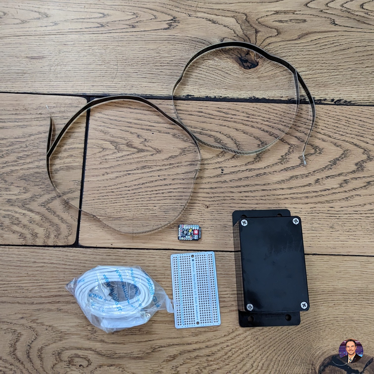
I use the M5Stamp Pico since it fits the requirements (2x ADC input) and the wifi signal is able to reach my network. You can use other ESP32/ESP8266 if that fits your project better, for example an ESP with external wifi antenna for better signal.
Initial programming of the M5Stamp-Pico
To get the M5Stamp-Pico talking to ESPHome we have to create a new device. I created with board type pico32 and called it 'bed-occupancy-master' (since this goes in the master bedroom, and if required I can then create additional ones for the other rooms). I then put in the following code as part of the esphome section:
  on_boot:
    - priority: 800.0 # after power up and hardware initialization
      then:
        - light.turn_on:
            id: builtin_led
            brightness: 100%
            red: 100%
            green: 0%
            blue: 0%
    - priority: 300.0 # after sensor setup, before WIFI initialization
      then:
        - light.turn_on:
            id: builtin_led
            brightness: 100%
            red: 100%
            green: 100%
            blue: 0%
    - priority: 225.0 # after WIFI initialization, no connection
      then:
        - light.turn_on:
            id: builtin_led
            brightness: 100%
            red: 0%
            green: 0%
            blue: 100%
        - delay: '00:00:05'
    - priority: -100.0 # everything is initialized, system is online - if condition waits for connection
      then:
        if:
          condition:
            wifi.connected:
          then:
            - light.turn_on: # indication of wifi connection confirmation
                id: builtin_led
                brightness: 100%
                red: 0%
                green: 100%
                blue: 0%
            - delay: '00:00:05'
            - light.turn_off: # turns off light waiting on automation to start
                id: builtin_led
This piece of code will use the interal RGB LED to show the status as follows:
- RED - Hardware initialization
- YELLOW - Most sensors are set up
- BLUE - Connecting to wifi
- GREEN (5s) - Connected to wifi
The LED will be green for 5 seconds before turning off.
Then at the bottom of the script (after captive_portal:) add the following code to create the required sensor entities:
light:
  # Create internal LED object for status
  - platform: neopixelbus
    type: GRB
    variant: SK6812
    pin: 27
    num_leds: 1
    id: "builtin_led"
    name: "Built-in LED"
    internal: true
    method:
      type: esp32_rmt
      channel: 0

binary_sensor:
  # Binary sensor for status of device
  - platform: status
    name: "Bed occupancy Master Status"
  # Binary sensor for left side
  - platform: analog_threshold
    name: "Bed occupancy Master - Left"
    sensor_id: bed_occupancy_master_left_value
    threshold: 0.4
  # Binary sensor for right side
  - platform: analog_threshold
    name: "Bed occupancy Master - Right"
    sensor_id: bed_occupancy_master_right_value
    threshold: 0.4

sensor:
  # ADC sensor for left TFP sensor
  - platform: adc
    pin: 32
    attenuation: 0db
    name: "Bed occupancy Master - Left Value"
    id: bed_occupancy_master_left_value
    update_interval: 60s
    internal: true # Default not exposed to front-end
    raw: true
    filters:
      - multiply: 0.00026862 # 1.1/4095, for attenuation 0db
  # ADC sensor for right TFP sensor
  - platform: adc
    pin: 33
    attenuation: 0db
    name: "Bed occupancy Master - Right Value"
    id: bed_occupancy_master_right_value
    update_interval: 60s
    internal: true # Default not exposed to front-end
    raw: true
    filters:
      - multiply: 0.00026862 # 1.1/4095, for attenuation 0db
NOTE: The 2 ADC sensors are not exposed to the front-end by default. If this is required for testing/calibration purposed change the internal value to false.
Here is the full YAML config I am using (Sensitive info marked with [REMOVED]):
esphome:
  name: "bed-occupancy-master"
  friendly_name: "Bed Occupancy (Master Bedroom)"
  on_boot:
    - priority: 800.0 # after power up and hardware initialization
      then:
        - light.turn_on:
            id: bed_occupancy_master_builtin_led
            brightness: 100%
            red: 100%
            green: 0%
            blue: 0%
    - priority: 300.0 # after sensor setup, before WIFI initialization
      then:
        - light.turn_on:
            id: bed_occupancy_master_builtin_led
            brightness: 100%
            red: 100%
            green: 100%
            blue: 0%
    - priority: 225.0 # after WIFI initialization, no connection
      then:
        - light.turn_on:
            id: bed_occupancy_master_builtin_led
            brightness: 100%
            red: 0%
            green: 0%
            blue: 100%
        - delay: '00:00:05'
    - priority: -100.0 # everything is initialized, system is online - if condition waits for connection
      then:
        if:
          condition:
            wifi.connected:
          then:
            - light.turn_on: # indication of wifi connection confirmation
                id: bed_occupancy_master_builtin_led
                brightness: 100%
                red: 0%
                green: 100%
                blue: 0%
            - delay: '00:00:05'
            - light.turn_off: # turns off light waiting on automation to start
                id: bed_occupancy_master_builtin_led

esp32:
  board: pico32
  framework:
    type: arduino

# Enable logging
logger:

# Enable Home Assistant API
api:
  encryption:
    key: "[REMOVED]"

ota:
  password: "[REMOVED]"

wifi:
  ssid: !secret wifi_ssid
  password: !secret wifi_password
  fast_connect: true

  # Enable fallback hotspot (captive portal) in case wifi connection fails
  ap:
    ssid: "Bed Occupancy Fallback Hotspot"
    password: "[REMOVED]"

captive_portal:

light:
  # Note: the built-in LED doesn't seem to behave correctly, and color control is flaky...
  - platform: neopixelbus
    type: GRB
    variant: SK6812
    pin: 27
    num_leds: 1
    id: "bed_occupancy_master_builtin_led"
    name: "Bed occupancy Master Built-in LED"
    internal: true # Default not exposed to front-end
    method:
      type: esp32_rmt
      channel: 0

binary_sensor:
  # Sensor status entity
  - platform: status
    name: "Bed occupancy Master Status"
  - platform: analog_threshold
  # Sensor left side entity
    name: "Bed occupancy Master - Left"
    sensor_id: bed_occupancy_master_left_value
    threshold: 0.3
  # Sensor right side entity
  - platform: analog_threshold
    name: "Bed occupancy Master - Right"
    sensor_id: bed_occupancy_master_right_value
    threshold: 0.3

sensor:
  - platform: adc
    pin: 32
    attenuation: 0db
    name: "Bed occupancy Master - Right Value"
    id: bed_occupancy_master_right_value
    update_interval: 60s
    internal: false # Default not exposed to front-end
    raw: true
    filters:
      - multiply: 0.00026862 # 1.1/4095, for attenuation 0db
  - platform: adc
    pin: 33
    attenuation: 0db
    name: "Bed occupancy Master - Left Value"
    id: bed_occupancy_master_left_value
    update_interval: 60s
    internal: false # Default not exposed to front-end
    raw: true
    filters:
      - multiply: 0.00026862 # 1.1/4095, for attenuation 0db
Once the device has been created, download the bin image file to upload to the M5Stamp-Pico over USB.
Connect the M5Stamp-Pico to the ESP32 programmer. Then use an Web Serial API enabled browser (Edge or Chrome) and use the https://web.esphome.io dashboard to upload the bin file to the M5Stamp-Pico.
Once the M5Stamp-Pico connects to ESPHome it will create the following entities on Home Assistant:

Test setup
As you can see in the picture below, the pins on the TFP sensor are delicate, so I already soldered the cable to it, and used heat-shrink tubing to avoid damaging it.
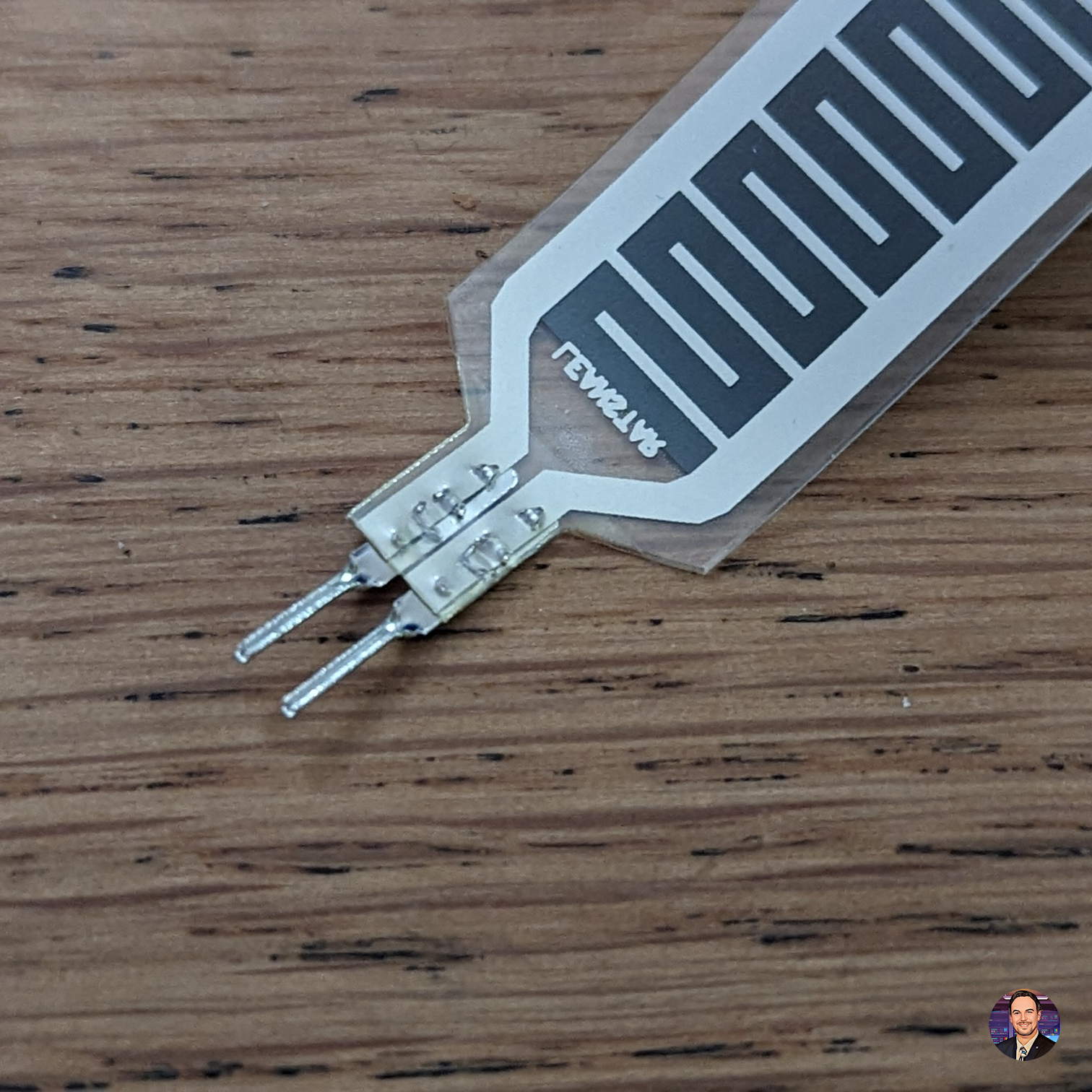
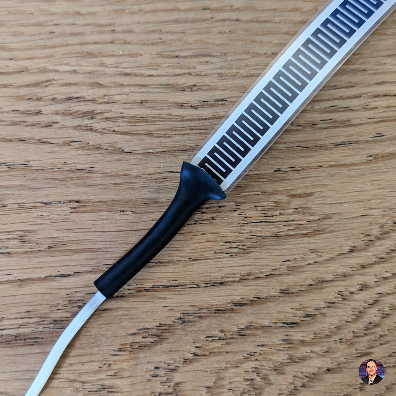
Now I can create the setup on a normal breadboard to see if it works as expected. I use the following design:
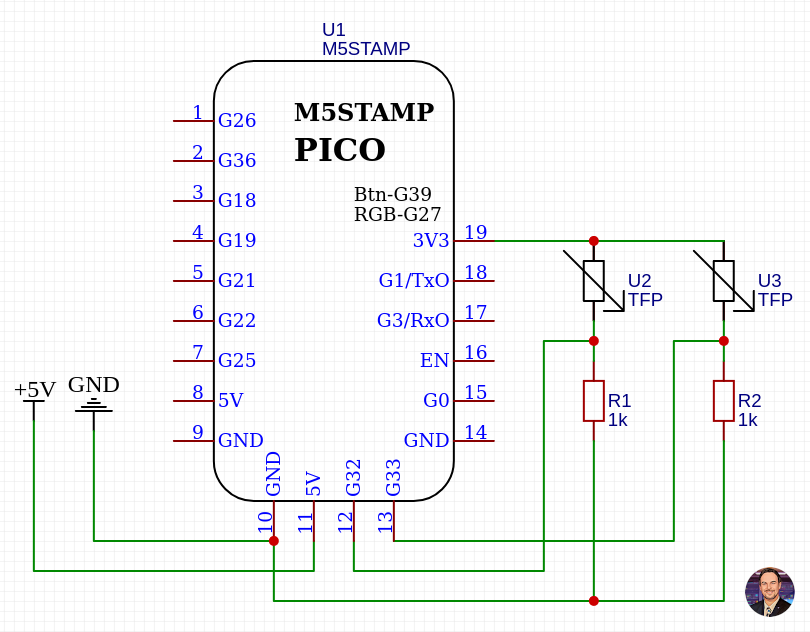
Pin 19 (3.3V) goes to both the 2 TFP sensors, the other end is connected to pin 12 (GPIO32) and Pin 13 (GPIO33) and both 5.1K Ohm resistors. The resistors are then connected to the ground.
Pin 8 (5V) and pin 9 (GND) are connected to the power from the USB cable.
Below is how my breadboard setup looks like for testing 1 TFP sensor. Since the 2nd TFP sensor is identical, but different pin, I don't need to test both at the same time.
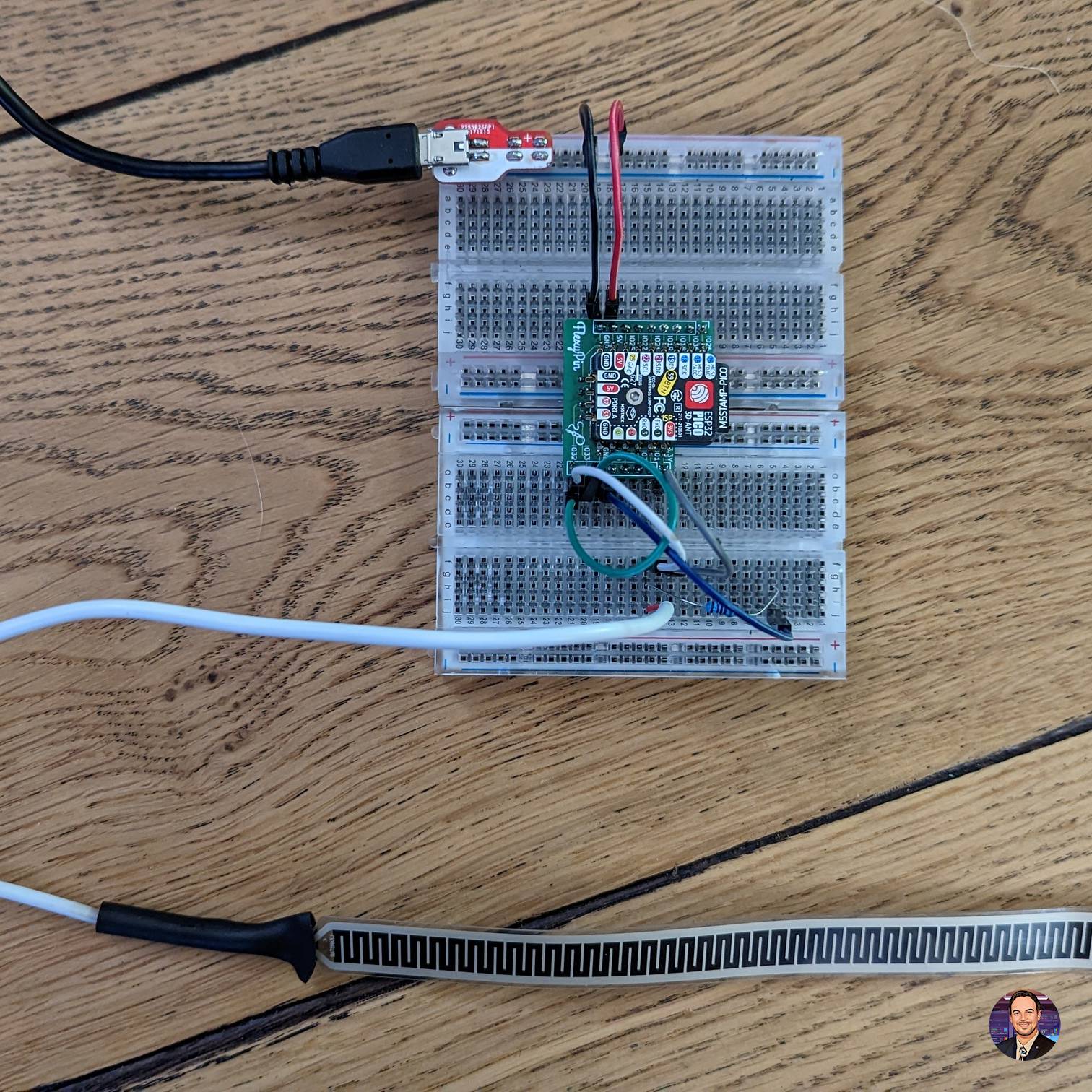
Once I have confirmed this is working as expected I installed it under the mattrass on one of the beams, I can test the values out. Initially the value is 0.0V, and once I sit on the bed it went up to 0.6V. So for now I use 0.4V as my threshold. I will now try it out overnight to see how it works.
The sensor seems to work as expected, and the binary-sensor was on for the whole night. Below is the graph of the ADC value overnight.

As you can see it isn't consistant with knowing I am in bed, since the threshold was 0.4 and it went below that several times. I will therefore lower the threshold to 0.2.

Now that I am happy with the setup, I can transfer it to the breadboard PCB and solder everything in place.
Final build
Now that I am happy with the setup, I can create the final build on the breadboard PCB, and put it in the box for protection.
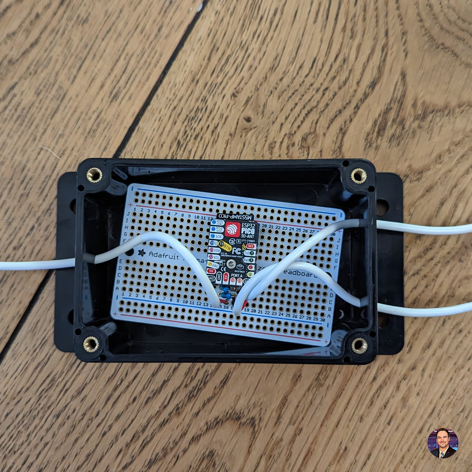
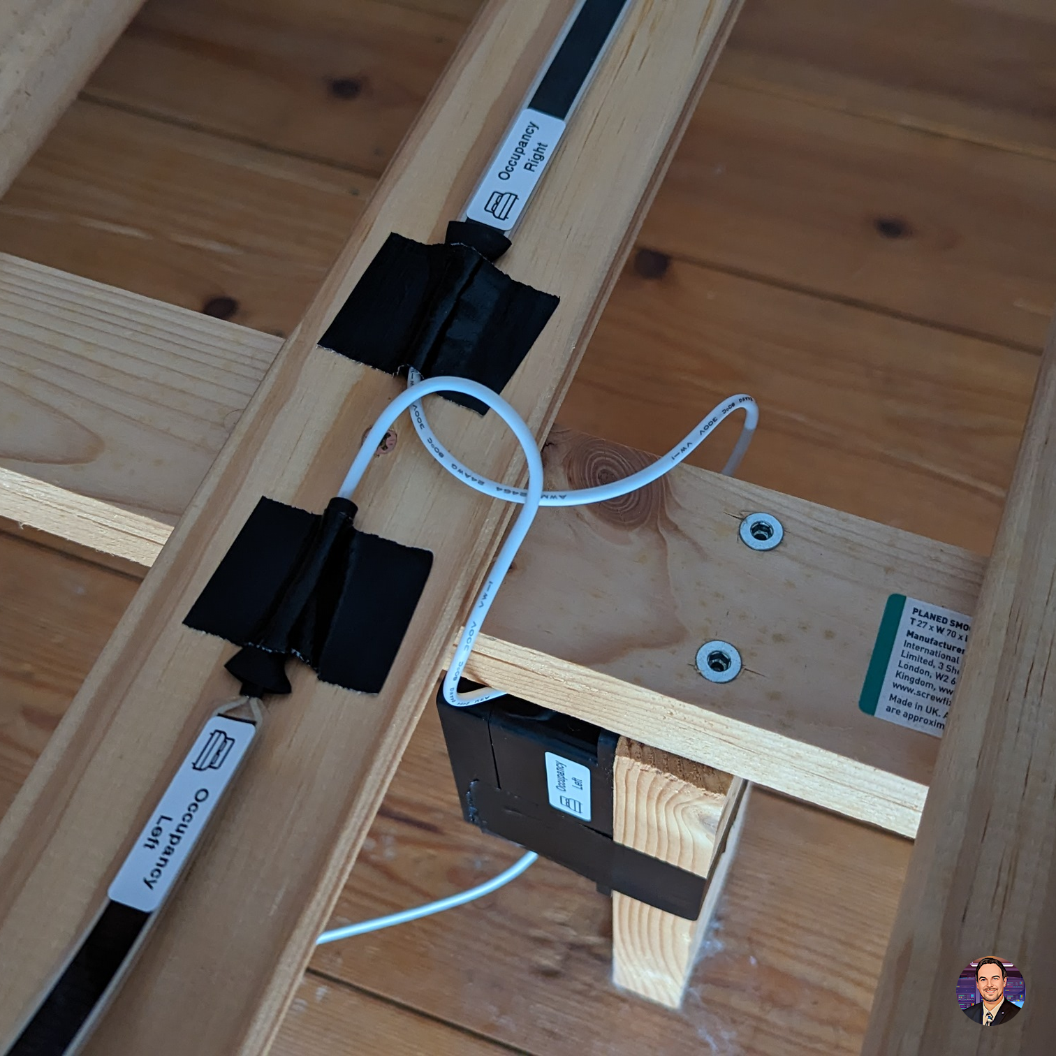
As it is properly installed it is time to create automations for when we go to bed, during the night if we need to go to the bathroom, and when we get up in the morning.
I hope you like how I create my little project, and if you have any feedback or comment then please let me know below.

